In short
A setting-out plan tells the build crew exactly where each wall, counter and column goes on the hall floor. It works from one fixed reference, usually a corner of the plot, and gives running dimensions along a grid. The crew marks these on the floor before anything is built. A good sheet removes guesswork on a tight build-up, and it stops the small errors that end with a stand overhanging an aisle.
Key points
- Every dimension runs from one fixed reference point.
- Running dimensions stop small errors adding up.
- Check the plot against the hall before you mark out.
- It differs from a general arrangement, which shows the whole design.
What goes on the sheet
| Item | Why it is there |
|---|---|
| Datum point | The fixed corner that all dimensions run from |
| Grid | Letters and numbers, so crew members can refer to a position by phone |
| Running dimensions | Measured from the datum, so that errors do not accumulate |
| Wall lines | The face of each wall, with its thickness shown |
| Fixed items | Columns, hall services and floor boxes on the plot |
| North or aisle marker | So the sheet is turned the right way on site |
Why running dimensions matter
If a drawing says 2.4 m, then 1.2 m, then 3 m, each small error on the tape is added to the next. A running dimension says 2.4 m, 3.6 m and 6.6 m from the same zero, so an error stays where it happened. That is the main difference between a setting-out plan and a dimensioned plan drawn for a client.
It also makes checking easy. A site manager can measure one long dimension and know whether the wall is right, without re-measuring the whole line.
Using it on site
- 01
Confirm the plot
Check the organiser's floor marks against your contracted plot and neighbours.
- 02
Find the datum
Agree which corner is zero, and mark it clearly on the floor.
- 03
Mark the walls
Tape or chalk out wall lines before the first panel arrives.
- 04
Check the diagonals
Measure both diagonals. If they match, the plot is square.
- 05
Note hall obstacles
Columns and floor boxes may not be where the plan shows them. Report them straight away.
A setting-out plan from the 3D model
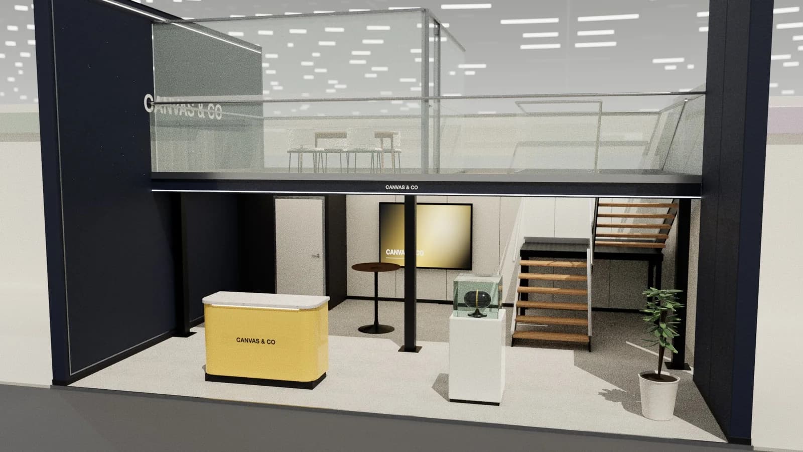
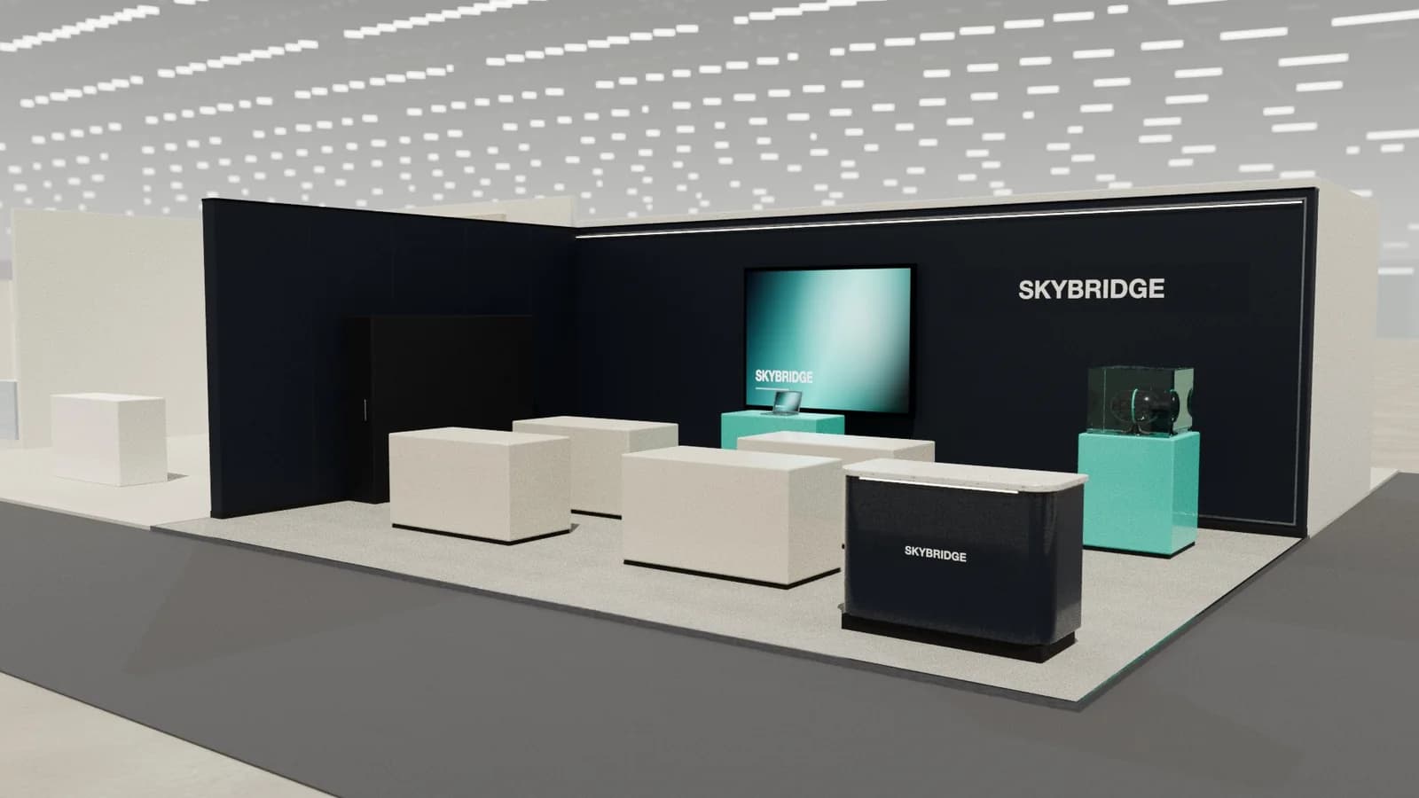
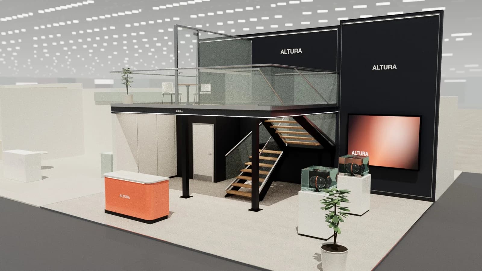
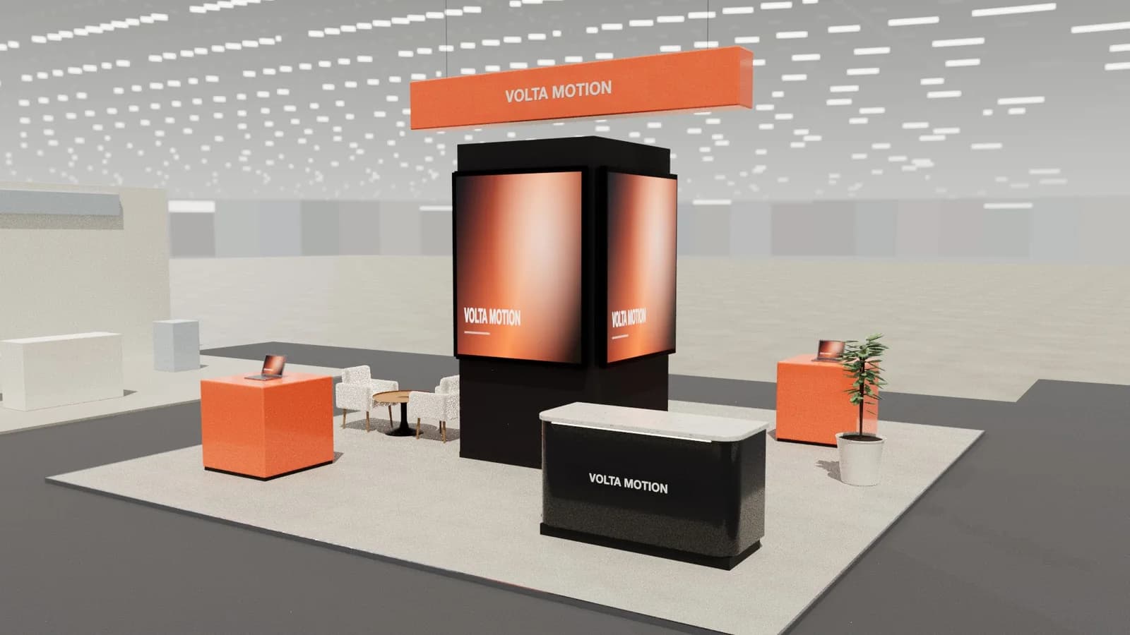
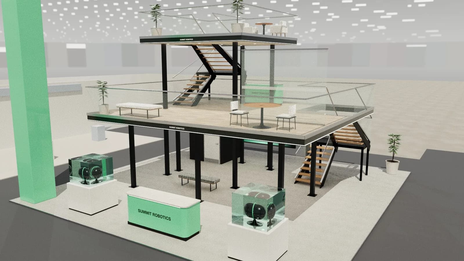
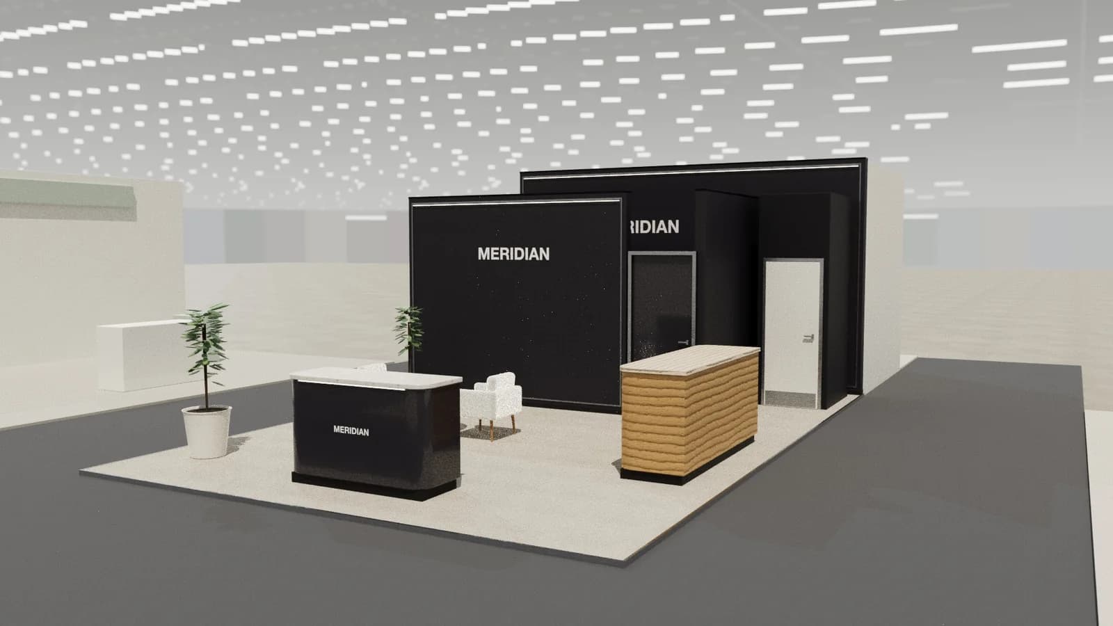
Studio's drawing pack includes a setting-out plan drawn from the 3D model, with dimensions from the front-left corner of the stand in millimetres. Because it comes from the model, it updates when the layout changes.
It is a concept drawing, so your builder should check it against the hall and their own construction. Editing and drawing export are free once a design exists; a new design costs 5 credits, and new workspaces get 5 free credits.
Frequently asked questions
01What is a setting-out plan?
A drawing that gives the crew the position of everything on the floor, using dimensions from one reference point.
02Is it different from a floor plan?
Yes. A floor plan shows the layout, while a setting-out plan is built for marking it on the ground.
03Do small stands need one?
A simple dimensioned plan is often enough at 9 m², but anything with walls or platforms benefits from one.
04What is a datum point?
The single fixed point all the dimensions are measured from, usually one corner of the plot.
Put it into practice
Exhibition stand technical drawings, drawn from the 3D design
A3 plan and elevations at scale, set-out grid, object schedule and a layered AutoCAD DXF, generated from the 3D design.
Guidance here reflects common practice. Venues, organisers and countries set their own rules: always check the exhibitor manual and work with a qualified stand builder and engineer for structures.